2% Δ silica channel waveguide (4.5×4.5 µm) ↔ SMF-28 at 1550 nm — segment width/duty optimized with a genetic algorithm driving a 3D BPM loss evaluation.
Target & SMF parameters
SMF-28 MFD is ≈ 10.4 µm at 1550 nm (vs ≈ 9.2 µm at 1310 nm). The last field is the mode-field diameter the SSC tip presents to the SMF (a design target the GA searches for). Set it equal to the bare WG MFD to see the loss without a converter.
n_core (from Δ)
—
n_clad (silica, Sellmeier)
—
Bare WG mode field diameter (D4σ)
—
Coupling loss — bare WG ↔ SMF
—
Coupling loss — SSC tip ↔ SMF
—
Improvement
—
SSC quality
—
Gaussian–Gaussian overlap model for a quick estimate; the real design objective is the 3D-BPM output power below.
Mode field cross-section — blue: SMF Gaussian, red dashed: bare WG mode, green: expanded SSC-tip mode. Larger overlap with the SMF means lower loss.
Why a spot size converter
The SMF-28 mode-field diameter grows to ~10.4 µm at 1550 nm, while a 2% Δ, 4.5×4.5 µm silica waveguide guides a much smaller mode — the mode-size mismatch is the dominant butt-coupling loss.
At the longer 1550 nm wavelength both the SMF mode and the waveguide mode are larger than at 1310 nm, so the raw mismatch (and the residual SSC loss) is somewhat higher than the 1301 nm design.
Expanding the waveguide-end spot to approach the SMF mode maximizes the overlap integral and cuts the loss.
A segmented (periodically broken) taper uses sub-/near-wavelength duty modulation to lower the local effective index gradually, expanding the mode adiabatically in a shorter length than a plain linear taper — and it respects mask minimum-linewidth rules.
Target: SMF coupling insertion loss < 0.35 dB at 1550 nm, with polarization and wavelength insensitivity.
Structure & design variables
The segment list is generated from a small parameter vector; the GA treats that vector as the gene.
Variable
Meaning
Search range (example)
pitch
Segment period (fixed along the device)
3.0 – 8.0 µm
n_seg
Number of dashed segments
35 – 100
duty_start / duty_end
Duty (fill / pitch) at the chip / SMF end
0.75–0.98 → 0.10–0.40
w_start / w_end
Segment width at chip (solid) / SMF facet
4.5 µm → 8.5 µm (fixed)
duty_profile
Duty ramp shape
linear / quad / cos
width_profile
Width ramp shape
linear / quad / cos
Duty violating the mask minimum linewidth / gap (e.g. 0.5 µm) is clipped or penalized in the fitness function.
Optimization workflow (GA ⇄ 3D BPM)
① gene → structure: the parameter vector builds the segment list (begin.z, width, duty) and the 3D-BPM index field n(x,y;z).
② 3D BPM run: launch the SMF-28 Gaussian at the wide low-duty facet, propagate, overlap the output at the chip facet with the guided chip mode.
③ fitness: Loss = −10·log10(η) [dB]; the GA minimizes loss. Robustness is checked over polarization and wavelength (1530 / 1550 / 1570 nm).
% Fitness (pseudocode)
function loss = eval_ssc(gene)
    idx  = build_index_field(gene);        % (1) gene -> n(x,y;z)
    psi  = bpm3d_propagate(idx, smf_mode); % (2) launch SMF Gaussian, propagate
    eta  = overlap(psi_out, chip_mode);    %     mode overlap at chip facet
    loss = -10*log10(eta);                 % (3) dB, smaller is better
    loss = loss + penalty(gene);           % min-linewidth / gap penalty
end
% GA driver: tournament select + real-coded crossover + Gaussian mutation.
% BPM is expensive -> search on a coarse grid, re-validate the winner on a fine grid.
GA optimization result @ 1550 nm
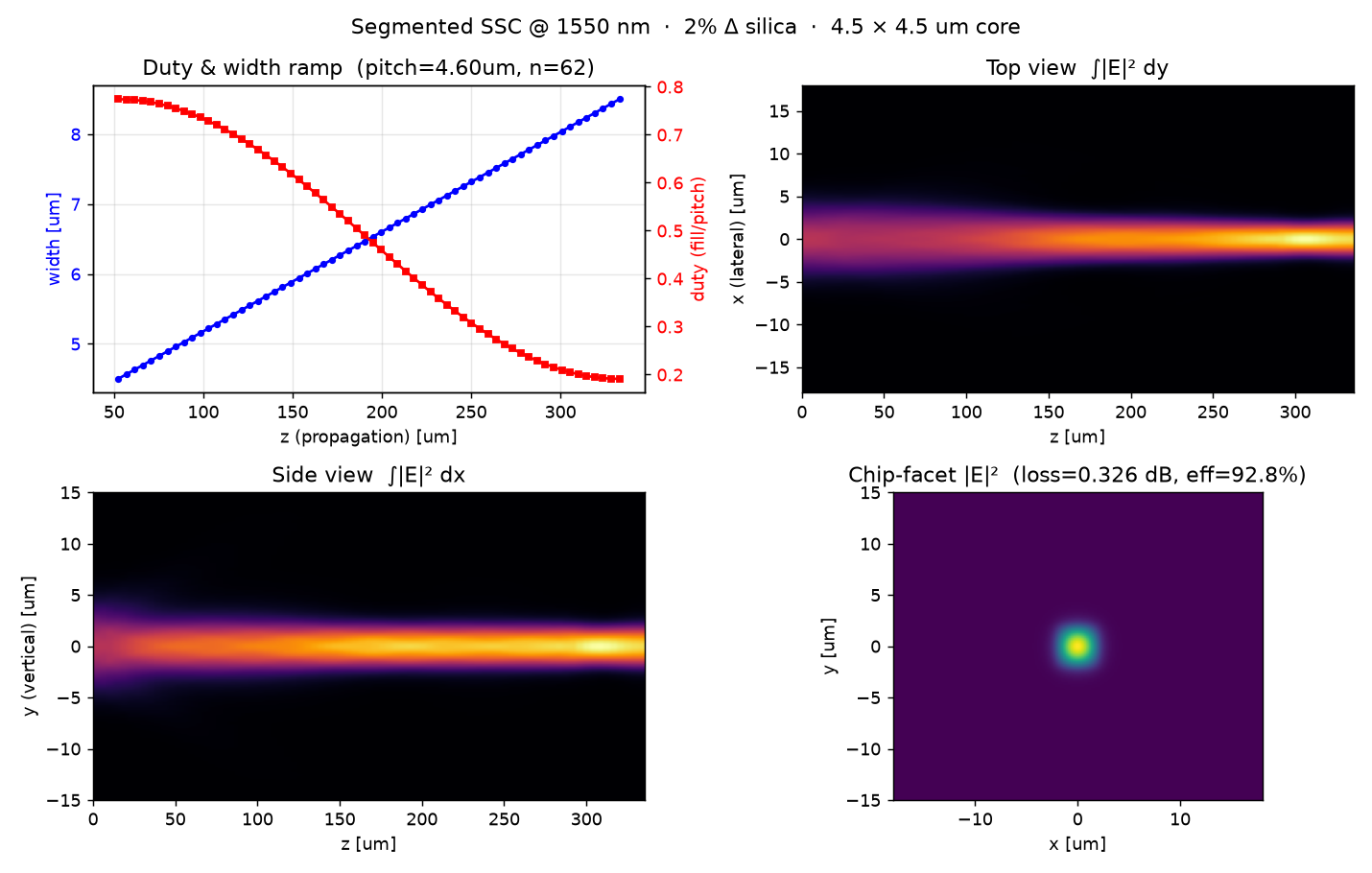
A pure-Python pipeline (gdstk segment generation → self-written split-step 3D BPM → genetic algorithm) was run for the target spec: chip waveguide 4.5 µm × 4.5 µm solid on the left, 8.5 µm-wide low-duty SMF facet on the right, thickness fixed at 4.5 µm, at 1550 nm on the 2% Δ silica platform. The GA freely tuned the pitch, number of segments, and the duty / width ramps. A 6-seed / two-facet-width sweep confirmed the design below as the lowest-loss condition.
Quantity
Optimized value
Coupling loss @ 1550 nm (fine grid, dx = 0.15 µm)
0.326 dB (η = 92.8 %)
Pitch / number of segments
4.60 µm / 62
Duty ramp (chip → SMF end)
0.77 → 0.19 (cosine profile)
Width ramp (chip → SMF end)
4.5 → 8.5 µm (linear)
Total device length
335 µm
Residual (non-radiated) power
0.969
Reference segmented SSC (un-optimized)
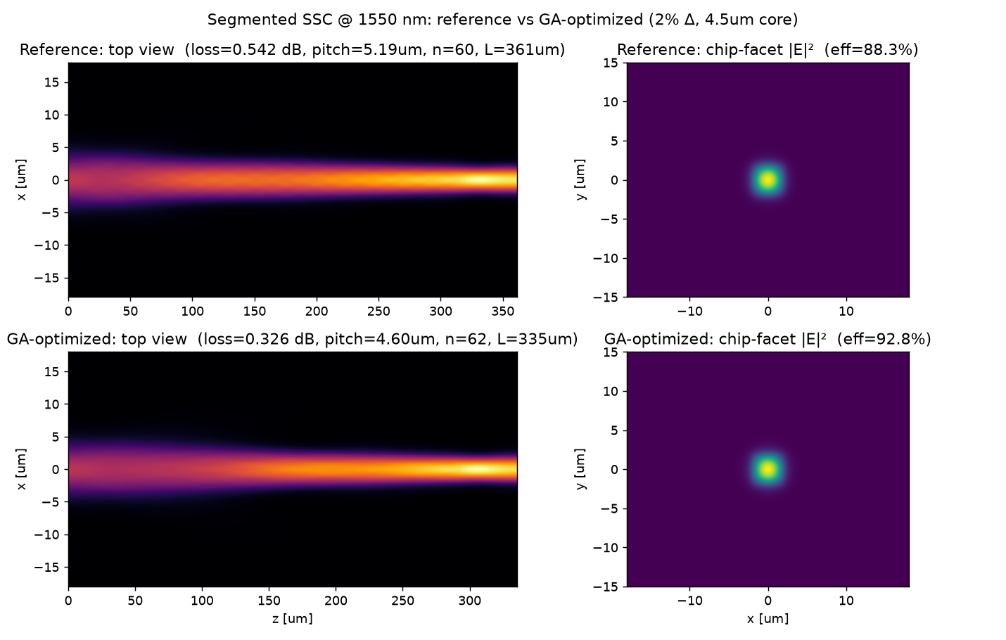
0.542 dB (η = 88.3 %)
The narrow solid end is a well-guided chip mode; toward the wide low-duty end the sub-wavelength segments lower the effective index so the mode expands to match the SMF-28 mode field (≈ 10.4 µm at 1550 nm). Launch is done at the SMF facet and overlapped with the chip mode at the opposite facet (reciprocity ⇒ same as chip→SMF). The GA cut the coupling loss from 0.542 dB (reference) to 0.326 dB, a 0.22 dB improvement.
GA-optimized SSC @ 1550 nm — duty & width ramps, top & side |E|² propagation, and the clean single-mode chip-facet output.Reference segmented SSC (0.542 dB) vs. the GA-optimized geometry (0.326 dB) at 1550 nm.
ssc_compare.png — reference vs. optimized comparison figure.
Run with python3 run_seg_ga_1550.py --pop 18 --gen 14 --seed 0 --out . (needs numpy, gdstk, matplotlib, and bpm3d.py). The GA searches on a coarse grid; the final candidate is always re-validated on the fine grid (dx ≤ 0.15 µm, window ≥ ±18 µm).
Equations
SMF mode (Gaussian): E_SMF(r) = exp(−r²/w²), w = MFD/2
Overlap: η = (∫ E_a·E_b dA)² / (∫E_a² dA · ∫E_b² dA), Loss(dB) = −10·log₁₀(η)
Index from Δ: n_core = n_clad / √(1 − 2Δ), n_clad from the Malitson silica Sellmeier model.